
MODIFICATIONS TO FALCON CONSOLE FOR ADDING POWER WINDOW SWITCHES
If you have a console that is like the one pictured, then a 1965 Ford Thunderbird center console window switch assembly could be used to provide a period correct looking installation by installing the new switches in the existing tray. The photo below is what a 65 switch assembly looks like in the Thunderbird console so you can see it would look right at home in the Falcon console tray:

For instructions for rebuilding your console and to remove the tray for adding the cutout required, please visit this page: REBUILDING THE CONSOLE
Alternately you may prefer the 58-60 console bezel:

The best place to look for the components if the Thunderbird switches are wanted to be used is probably going to be ebay, but some of the T-bird suppliers have new parts although quite pricey. A link is provided at the end of this page. Another thing to consider is the 60s model Fords used a 3 wire motor for the windows, an UP, DOWN and COMMON wire. The new motors are 2 wire and the polarity is reversed for the UP and DOWN. So if early switches are to be used relays can be wired to accommodate the 2 wire motors. The schematic is shown here:
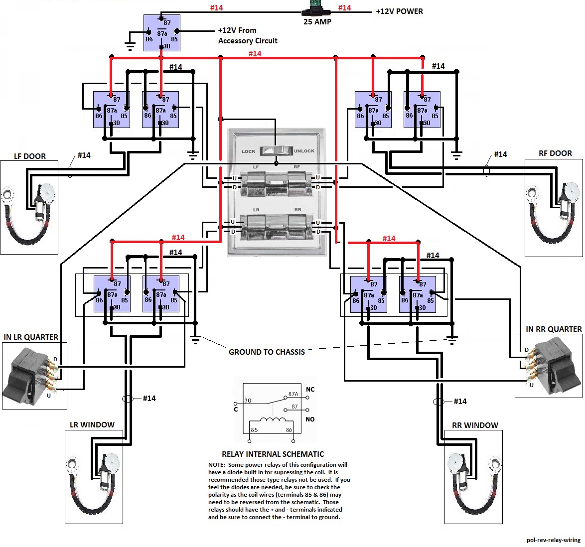
Now since this will not be plug and play, it will be important to make sure of the up-down wiring of the switches. What I recommend is to identify the up terminal that is connected to the common terminal when the switch is pushed to the up position. Generally Ford switches of this era will have the common terminal in the center and with the switch in the operating position, the up terminal will be the lower terminal on the switch as illustrated above by the rear switches, but some switches will have a different terminal layout so it is best to identify the common, Up and Down terminals. It is going to be best to verify this with a continuity tester. Once the Up and Down terminals are identified be sure to connect as shown in the schematic. After hooking everything up, if a window operates in the wrong direction then the window motors wires at the window motor should be reversed.
Component Location
The window switches are mounted in the tray of the stock console by carefully cutting a rectangular hole in the console tray and underside. I personally would prefer using a Dremel rotary tool with a cutting wheel for this as some other type of saws like a saber saw could damage the tray. Pay attention as to how the switch bezel is mounted in the console as there may be some special notches required to accommodate the mounting. The window switches should then just snap into to bezel from the underside with some spring clips.
What console switches you decide to use will be up to you, of course, and is somewhat out of the scope of this document as the main purpose for this document is to be able to use the older switches intended for use with the older three wire window motors with the new two wire window motors.
You may want to use other older switch assemblies where the master switches are mounted in or on the driver's door like what would be used in the full size Fords of the 60s era. Most of the suppliers that cater to the older Ford Thunderbirds will be a great place to start. The '58 through '63 T-Birds had door mounted switches and if you choose the T-Bird switches, I recommend the '63 model switches and bezel because the '63 used three wire window motors. The earlier models used a four wire window motor. The bezels should be the same, so only the switches need to be the '63 versions.
Now back to locating the components. If you are going to locate the switches in the console then I would recommend locating the relays under the console or under the back seat. The simplest location is probably going to be under the console if there is sufficient room. You could also locate the relays for the front windows under the console and the relays for the rear windows under the rear seat.
Relay Preparation
If you use female disconnect terminals individually on the wires vs a relay socket pigtail then the relays can be set up in pairs as shown in the following illustration:

The jumpers can be made with bare #16 ga wire for the ground and either bare or red insulated #16 ga wire for the +12V. If you are going to use relay socket pigtails then all of the solder joints will need to be close to the relay as shown for the +12V jumper instead of routing through the terminal holes so the socket can be pushed on. Also if you decide to use the relay socket pigtails you may want to remove the unused terminals or clip the wires at the socket. Of course you can just tie the pigtail wires together in lieu of soldering to the terminal relays which is what is implied in the schematic. Preparing the relay pairs as shown with the jumpers soldered to the relay terminals will just simplify the wiring at the relays and make the install look a bit cleaner. The downside to preparing the relays with the soldered jumpers would be if a relay should need replacing, then the new relays will need to be prepared in pairs before replacement.
Component Sources:
Relays: Absolute USA RLS125-10 SPDT 30/40A 12 VCD Automotive Relay - 10 Pack
2 Window Kit for Ranchero: FULL COMPLETE CAR TRUCK 2 WINDOW AUTOMATIC POWER KIT WITH 3 SWITCHES KIT
4 Window Kit: FULL COMPLETE CAR TRUCK 4 WINDOW AUTOMATIC POWER KIT WITH 7 SWITCHES KIT
Relays with socket pigtails: Genssi (10 Pack) 30/40 AMP Relay Harness Spdt 12V Bosch
#14 ga Wire: Trailer Light Cable Wiring For Harness 50 ft spools 14 Gauge 7 Wire 7 colors
Shrink Tubing: Handysmart 127 pc Heat Shrink Wire Wrap Cable Sleeve Tubing Sets Assorted Size e/Case
#16 ga Wire: 6 SPOOLS 100' Feet 16 GA Gauge AWG Primary Remote Wire Auto Power Cable Stranded
Console & Quarter Switches: Thunderbird Components from Mac's Auto Parts
Tools used:
Soldering Station: Weller WLC100 40-Watt Soldering Station
Dremel Rotary Tool: Dremel 4000-2/30 120-Volt Variable Speed Rotary Tool Kit
Dremel Accessory Kit: Dremel 710-05 160 Piece Accessory Kit